MOSFET FREQUENCY COIL - device (MFC)
A project of the german Lyme-and-Rife group Link
MFC-group in English Link
Introduction
A few words about how this device came around.
A while after founding the lyme and rife group over here in Germany we started to have members with electronical knowledge. Since we were familiar with the idea of the doug-device it's been our goal to realize one. The problem over here is that eg. the QSC-1850 isn't sold in europe, so untill today we do not have a reg. doug-device! Outside of the group I had a team of scientists working on something like a mega-doug with "helmholtz-coils".. they're still working on it, but it takes them ages, because it's only one of their side-projects and they don't have lyme. In our group Stefan, member-name "bigboppa", became our main Research & Develpment specialist. What we had was a homemade pulser that Stefan made and another one I once ordered from Robb. Simultaniously we were still treating our lyme somewhat successfully with our frequency-generators as contact-devices like many others in our group do. Weeks went by untill Stefan had the brilliant idea to make his pulser "do frequencies", this was last June. It still wasn't a real doug but it was a pulsing frequency coil device that had us herxing well - everytime we used it. I have tryed it on non-lymies and they had no reactions, unlike people who have lyme. We posted about this instantly in your group and together came up with the name for the "new" device: MFC : mosfet-frequency-coil....(device). In the discussion it was mentioned that the MFC, including both, PEMF and MORs, represents a potential idea.
Stefan refined the MFC and so far has made about 15 units for members in our group. Another 5 units have been homemade by able members of the group. The idea was to make a potential "do it yourself" rife device available, simple and low in cost. It's copyrighted to prevent others from doing so. If you don't want to make one, or if you're not able to make one, or if it looks like more work than Stefans' price, or if you simply want an original, you're wellcome to contact Stefan. The basic MFC-unit is handmade for 230.- euros. He's is also working on a running prototype of an AC-MFC, which comes closer to the orig. doug-device.
Since it takes up to 2-3 years to find out if a certain device can get one all the way out of lyme, we don't know yet where the getting better will stop with the MFC.
I thank everyone involved in the process of bringing ideas together! Pascal
MFC-Unit:
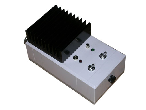
This is how the MFC-unit looks. You see an early model without the cooler and the "Line-In"-option.
The MFC with it's special circuit creates Magnetic pulses in rates from 1Hz up to 80000Hz. The use of the known Rife/Doug/CAFL frequencies has proven to be effective with this device. It can run with (1),2,3 and 4 batteries (12, 24, 36 or 48 V). The standard use is 2 batteries, 24 Volts. The use of 4 batteries, 48 V is not recommended for "beginners", as the herx is hard to control with the stronger field. (double voltage makes the field 4 times stronger)
The higher the quality coil the less losses it creates and the cooler it stays (it should be evenly wound, best made professionally from lackered coil-wire instead of plastic-coated wire). Homemade coils work too but get hotter sooner and have a less homogenic field. We made coils out of 100 meters of a 4 square-mm wire, coil-diameter 22 cm. More recently we have 2 sizes of coils custom-made, ready to order from a professional maker for every member. From abroad it's possible to order those coils through Stefan.
The complete setup includes 2 Batteries, a coil, the MFC-unit and a "frequency-device":
The latest MFC includes a LINE-IN-Pre-Amp that gives you a choice of Set-ups by using different frequency-sources, which does not influence the effectivness:
1. You can use a Frequency-Generator, it needs to have square-wave-, sweep- and symmetry functions. This way you have to adjust the single frequencies and sweeps everytime you treat. ..free to use what ever frequency you want to choose. Expensive piece of equipment. (>250.-)
2. We created a file section with frequency-sweeps that loop of the website and that you can run of the soundcard of your computer into the LINE-INPUT of the MFC. This way you save the money for a generator. Since the MFC needs an asymmetric signal with a pulse/pause ratio of abot 1/3, these files are custom-designed: sound-frex-loops (under construction). If you find or have a virtual frequency-generator on your computer with all the needed functions it will work fine too!
3. We are in the process of creating a CD that comes with the MFC and that you can run from any CD player into the MFC. Every CD player can repeat tracks, some can even be programmed to play tracks in a certain order. So you can choose from different single sweeps and combined ferquency sweeps in different CD-tracks. In fact to get a full treatment one can just run the whole CD and actually run the whole CAFL List for Lyme and coinfections in one treatment of the length of the full CD (imagine the ton of work adjusting all these frequencies one saves). This is the cheapest way, no need for a computer or a frequency generator and it's the most comfortable way to treat, without having to look for, choose and adjust frequencies all the time. You might load these CD tracks into your computer to shuffle the tracks or design your own little treatment-sequence. CD will be free to download from the web. (preferably fast DSL connection)
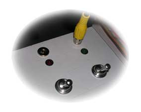
Control Elements:
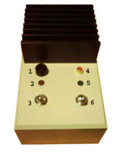
1: Fuse for the relay, not for the main current path
2: Control LED 1 for the main switch (red = switched on)
3: Main switch (downward = OFF, upward to the LED = ON)
4: Input jack for the signal of the frequency generator (Cinch)
5: Control LED 2 showing pulses (green = MFC DEVICE is pulsing)
6: Pulse-signal switch (downward = OFF, upward to the LED =ON)
Line-input jack and cooler are added on newer MFCs.
A faulty operation by a wrong switching sequence is impossible.The designation of the switches is not fixed, the first switch, which is switched upward, switches on the MFC DEVICE, second switches on the pulsing.
connecting the MFC-DEVICE:
Both switches at the MOSFET DEVICE have to be on OFF
(away from the LEDs)
when connecting the device with the batteries and coil!
For the complete MFC-DEVICE you need:
MFC-Unit,
2 car batteries,
the coil,
your choice frequency device (FG or Computer-Sound-Output or CD)
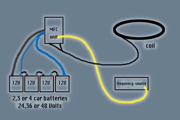
schematic of the complete MFC-device without charger(s)
connecting the batteries:
2 car batteries are needed (approx. 40 Ah or more). The contacts of the batteries and to the coil must bear high current. For 4-sq.mm cable we use connectors with a 6 mm hole, there is also car batteries with punched, rectangular connectors, not the normal round ones. The wiring has to be connected as in the following picture:
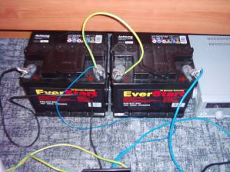
Wiring for 2 batteries, 24 Volts.
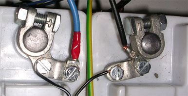
connectors on reg. round type.
The black thick cable of the MFC DEVICE is connected to the negative pole of the battery 1. The blue thick cable is connected to the positive pole of the battery 2. The green yellow thick cable with the thin blue cable connects the two batteries: One end goes to the positive pole of battery 1, the other end goes to the negative pole of the battery 2. The square connectors come with bolts, for the round connectors, you find on regular car batteries, you need round connector pieces to screw the MFC cables onto. Every few weeks one should check whether the nuts/screws are still firm, since the lead of the battery poles is very soft and can deform.
battery charging
The battery charger shown at the photos is the german model designed for 230V input and 24V output. Abroad you need to find your own. Take care to buy an automatic loader for lead batteries, because they do not overcharge the batteries. (approx 300-500mA, 24 V). This way the charger can allways stay connected.
If you have a cheap (nonautomatic) loader, you can use it but you have to disconnect it as soon the batteries are full. Otherwise, if overcharged, the batteries will produce explosive gases and at the next time you close the switch of the MFC you might ignite a "final treatment".
connecting the coil:
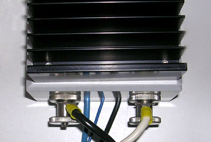
The two cables of the coil (here black and white cables) are fastened under the two large knurled thumb screws. Please pay attention to a good connection because the MFC in operation will heat up. The worse the connection is, the hotter the screws become...
A few words on winding the coil if you want to make your own: The more evenly the coil is wound the more homogenic the magnetic field will be and the smaller the losses. We use 100 meters of 4-sq.mm braid wire for a coil with approx. 22 cm inside diameters. Total resistance 1 Ohm. We also have used coils of magpulsers, you can practicly use the same coil for both, the magpulser and the MFC, at least to try the MFC and maybe later upgrade to a pro-coil.
For a better field we have two sizes coils professionally custom-made and to be ordered by group-members from the maker. People from overseas can contact Stefan for such a coil.
connecting the frequency-device:
picture coming up soon!
For connecting the Computer or CD-player use the Line-in jack.
For connecting a frequency generator use Cinch-input (4.)
When everything is connected it looks like this:
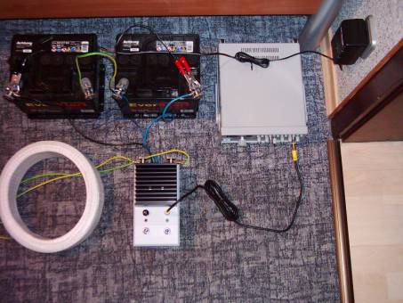
in this case a generator and a prototype coil is used
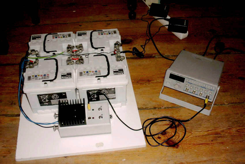
This picture shows an MFC-device with 4 batteries (48V) and two chargers, the FG-7202 and no coil.
Now when everything is connected, you're ready to start the treatment. First turn on your frequency-device (FG, Loop or CD), than the main switch (nr. 3) and last the signal switch (nr. 6)
You will hear a humming sound coming from the coil. This indicates that everything is working fine. If this sound is missing and the coil is heating up, turn off the main switch immediatly and have your device and coil checked!
To turn off the device go about in reverse order. Signal-switch, main-switch and frequency-device.
Settings for a Frequency-generator (FG)
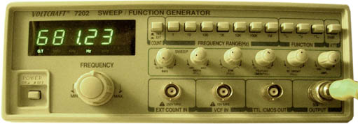
(This part refers to the model frequency generator we use in the german group, the FG-7202 for 259.- euros, you don't need to apply this chapter if you use the Computer or the CD-player as a frequency-source)
Theoretically any another frequency generator can be used, it must have an output voltage of 20Vpp (pp = peak to peak) at the open output. With smaller voltage the MOSFET DEVICE can take damage. It needs to have a symetry control to design the signal for the MFC. What it needs is a pulse/pause rate of appr. 1/3.
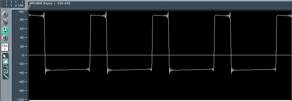
Audio-waveform of a "sound-frex-loop" showing pulse/pause ratio.
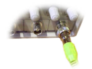
The FG 7202 is attached with the provided Cinch cable and the BNC Cinch adapter to the jack "OUTPUT" of the FG-7202, jack "4" at the MOSFET DEVICE:
Main switch and Signal switch on the MFC are switched OFF !!!
All parts are completely connected !!!
Adjustments on the FG 7202:
SYM-knob is pulled out, to 9 o'clock to maximally 12 o'clock set to button SYM. (I have approx.. 10,30 o'clock adjusted) pulse/break is stopped here the relationship: To central position (12 o'clock) the pulse becomes longer, the coil warmer therefore. Longer is better, but the coil may become however not too hot! Over central position it becomes again worse and still hotter, which brings thus nothing - better switch off (button purely) if the coil goes through. It is by the way all the same to the MOSFET.
Adjusting the frequency: the higher the frequency the warmer the MFC gets. On lower (>1000 Hz) frequencies it's the coil that heats up primarily. The MFC runs frequencies from 1 Hz up to 80000 Hz. Above 5000 Hz you have to check if you can still touch the heat sink, if not, please switch off and let cool.
SWEEP (= Wobbel) as required: RATE completely on SLOW, WIDTH for upper critical frequency, WIDTH - button for switching on pull out.
in NO case pull DC offset, button must purely!!!
AMPL at MAXIMUM !!!
FUNCTION at Square Wave!!!
20dB ATT inactive.
control the points 4,5.6 a second time, them are vital for the MOSFET transistor!!!
to turn on the unit first switch the main switch, then the contactor closes and the MOSFET DEVICE is ready to operate. Then switch on the signal switch. If it is all OK, both LEDs are alight, LED1 indicating voltage supply and the LED2 the pulses.
Here we go..., if the SYM is readjusted, because e.g. the coil becomes too hot again, you have to correct the frequency adjustment as it changes too by changing the sym.
To turn of the unit, first signal-switch OFF then main switch OFF..thenFG off.
If the coil continous to get too hot although SYM is minimal, possibly a component has gone defect: Normally you can hear the coil, which corresponds to the frequency. If the sound is missing, something's wrong. (or the frequency is too high, 10000 cycles per second is hardly to be heard)... first switch off the signal switch, if LED2 goes off, everything is correct, then only the coil could be defect. If the LED2 remains on, the MOSFET is defect, if so, hurry to switch off the main switch!
For testing the Set-up adjust a frequency of 20 cycles per second. LED1 must illuminate after switching on of the main switch, expire after switching off slowly (approx. less than 1 minute). LED2 must pulse after switching on of the main switch and the signal switch with 20Hz and give the coil a deep tone of itself (very quietly). One can bring the coil closer carefully to a switched on television or monitor (no TFT or plasma), if the picture is wobbly, is all ok. Caution, hold the coil not too close at televisions or monitors, otherwise this can harm the screen.
additional information:
If the unit is in operation, never loosen the coil-connectors!
!DANGER!
High voltage!
Always switch OFF both switches before loosening the coil connectors !!!
This is purely a documentation of how we use this experimental device. It's the users risk and responsability to do treatments with the MFC-devide. Pregnant women and people with pacemakers cannot use the MFC.
This is an experimental device.
Nobody but the user takes full responsability for any damge done by this device.
Here some ideas concerning the risk of using devices like the MFC:
The strenght of magnetic fields is meassured in Tesla (T), it used to be Gauss. (1 tesla= 1000 Gauss)
here's a list of known magnetic fields:
0,0000002 T limit for transformators in the US
0,00005 T magnetic field of planet earth
0,0002 T limit for transformators in the Netherlands
0,0003 T limit for transformators in Germany
0,0065 T MOSFET-Device with a 45cm coil (100m*4mm^2) (at 24V) (65 Gauß)
0,02 T MOSFET-Device w 22cm coil (100m*4mm^2) (at 24V) (200 Gauß)
0,032 T MOSFET-Device w 22cm coil (100m*4mm^2) (at 36V) (320 Gauß)
0,044 T MOSFET-Device w 22cm coil (100m*4mm^2) (at 48V) (440 Gauß)
2 bis 4 T MRT (Magnet Resonant Tomograph)
25 T Strongest artificial field ever realized
Frequencies in magnetic fields below 100.000 Hz are considered "Low Frequency" and have no thermal effect on body tissue.
Long term exposure to high-frequency magnetic fields are questioned to have bad effects on the organism.
best wishes, good luck!
Stefan & Pascal
Look in the groups' file-section for d.i.y. schematics and partlists:
back to group
WARNING!
DISCLAIMER: The publishers of this information are not doctors and are not qualified to give medical advice. This website is informational and educational only, it's not intended to prevent, diagnose, treat or cure disease. Rife machines are experimental and may carry risks and side effects.